Kawasaki Motorcycle Forums banner

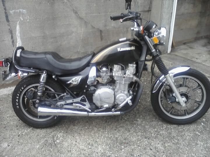
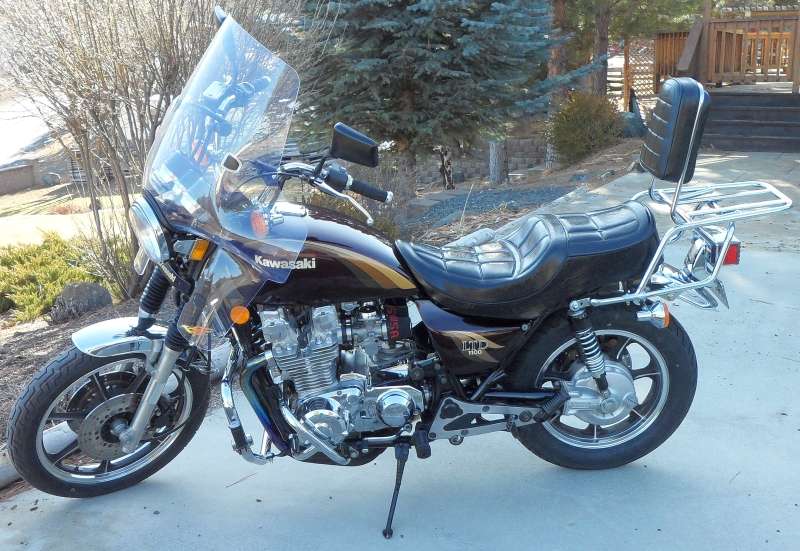
New to me 1983 kz1100 ltd looking for some info

1 reading
17K views 24 replies 5 participants last post by  KawiBGB  
#1 ·
I have been looking for an old big cc kawi for a while and came across an 83 ltd1100 with a rebuilt motor for a cool $1000 bucks. Ive been riding for a while so this is not my first bike, but my first old bike. It runs good and has good power, but I am not completely crazy on the looks and want something more aggressive looking. I have a few questions how is the power compared to a typical kz1000 with a chain drive vs this bike with a shaft drive. I have no complaints about power its got plenty of pull, just curious if they are even in the same league? What parts are compatible with the kz1000 and kz1100, I like the tank and rear fender alot on the kz1000 as well as the handlebars. I figure I got a good deal on it at 1000 since there is no rust or dents and the motor has been rebuilt within the last couple thousand miles and every kz1000 ive seen around here is either a huge mess or its a serious dragbike, so its a good platform for a muscle bike. I just shelled out 189 for the tags and title and 100 for tires, so im not that far deep into it. Any ideas would be awesome thanks!
Image
 
#2 ·
The differences are that a shaft is almost maintenance-free but less efficient than a chain putting the power to the ground. The shaft is also iheavier than the chain making these bikes a tad slower than the standard ones. But nothing you would really notice, unless you were racing. The engines for shaft or chains had same power.

Shafts were given to these models (LTD and ZN)because at the time they were Kawasaki designated cruiser immitator versions of the KZ, which as the sportier "standard", and they were supposed to be slow boulevard riders not canyon carvers. The differences between LTD(ZN) and KZ were cosmetics and geometry.

Of more concern may be the handling characteristics, as the shaft tries twisting the frame in the opposite direction, but again, it wolud only matters if you were racing, other wise just be aware of it.

The 1100 is a bored out 1000.
 
#3 ·
This is definitely a "different strokes for different folks" sort of issue - whether to leave an old classic as it is - or try to make it into something else. I bought mine BECAUSE of what it is, looks like, and rides like, so have preserved that as much as possible.

http://www.kawasakimotorcycle.org/forum/vintage-motorcyle-info/143034-winter-project.html

BUT, while restoring and upgrading mine, I couldn't help but admire the neat bobber-style look with the tank and seat off - and could just imagine it with a Harley style peanut tank and a solo seat. I ended up with what's seen below, no regrets - and while there might be a slight loss of drag-racer performance of a shaft vs chain drive, the convenience of the shaft more than comphensates, as far as I am concerned - I've had all chain drive types before this LTD - and am serioualy glad to be free of slung lube, and constant chain adjustment/replacements.

Yours looks great - good luck, whatever you decide to do to it in the future!


#4 ·
Thats very good info, I am not planning on going and hitting the twisties with this bad boy I have an 09 zx6r for that haha. I mainly want to swap over some of the parts I like off the KZ, such as the rear tail which I think should bolt right on? and handlebars, because the ones on there are killer on my wrists. Is that possible to do without changing all the cables?

I want to keep it looking tough, not going for the bobber rat bike thing, I want something that looks like a mean old jap muscle bike, low bars, nice paint and a nasty exhaust, basically try to make it look like a factory custom and not something someone slung together and chopped up. The motor on this thing is beast!
 
#8 ·
I also noticed a ticking sound in the top of the motor today when i started it up cold, it sounds like a metal on metal tap from the valves, however the motor was rebuilt a few K ago. Where can I find how to check the valves, do I need a new gasket if I do, and where do I get the shim kit if it needs them?
 
#9 ·
Here's what you need:

KZ1100 - Manual

Checking valve clearances

When I do my readings I always have the lobe of the cam pointing away from the shim bucket. I do not go in the order that the manual states. I do one side then the other side.
roy-b-boy-b (User)

Re:Valve clearances
Then you can use your feeler gauges
Start with the minimum (thinnest) gauge and check the clearances.

If you can't get the feeler gauge between the cam and the shim, check and see if you can spin the bucket with your finger. If you can, you do have some clearance but not enough.

I don't have my manual in the house so I don't know if your clearances are in tolerance.

If the big numbers are showing too wide then you can swap them to the valves that have no clearance to see if that will bring them into the proper tolerance Roy

Patton (User)
Re:Valve clearances (is this correct way to read them
Aim for 0.05~0.10mm (.002~.004in) clearance for each valve, measured with cam lobe pointed directly away from the valve.

Shim sizes come in .05mm steps. For example, with a 2.75mm shim, the next thinner shim is 2.70mm, and the next thicker shim is 2.80mm.

The existing shim must be removed (special tool) to read it's size on its underside. If the number is illegible, a caliper or micrometer may be used to measure its thickness.

As Roy mentioned, where clearance is insufficient, but the shim turns, there is some minimal clearance. So the next size smaller shim will likely suffice. If there's zero clearance and the shim won't turn, probably needs a shim two sizes thinner.

Typically, the existing shims may be mixed around to gain proper clearance for some of the valves.

Re:Valve clearances
Here's the way I was tought by factory Kawasaki mechanic Keith Pestotnik RIP.
Turn engine over slowly while constantly trying to insert a .05mm feeler. If it fits, constantly try to insert a .10mm feeler and so on to find the largest feeler in .05mm increments that will fit at any rotation of the cam. Do this on all 8 valves. Call this your clearance, so if a .10mm fits and a .15mm does not, call .10mm your clearance. Do this on each valve. I try to get all at .10mm. Sure some may be .11mm, some .13mm ect, but who cares? Shims are available in only .05mm increments so if I changed a .11mm out for a larger shim I would then be at .06mm. Doing this way I know all my valves are between .10mm and .15mm right where they should be.
It drives me nuts reading how guys check their valves using 100 feelers. Does it really matter if valve #1 reads exactly .129mm? Lot's of wasted time. Valve shims come in .05mm increments, no need to measure to scientific 1000ths of a MM because you can't change settings except in .05mm steps.

Re:Valve clearances (is this correct way to read them
I take the spark plugs out and use a wrench on the end of the crankshaft (by the points) to turn the crankshaft until the cam lobe is pointing directly away from the lifter bucket. In other words, a line through the cam would be at right angle to the flat face of the lifter bucket. Turn it ONLY in the direction of normal engine rotation, don't reverse direction.
 
#10 ·
Lots of air-cooled engines will be noisier cold than when they are fully warmed up - let the engine come up to temp, then check for unusual noises before you start tearing into the innards...

The vendors on this website offer various gaskets and parts, and EBay motors is a good source of parts for older bikes as well...

And yes, you will need a new gasket if you take off the valve cover.
 
#11 ·
I will give that a shot, I also think changing the oil is a good idea as well. I have no clue when the last owner changed it so that could also be a cause, gotta try the easy stuff first, just waiting on a filter I ordered. If I change the bars to something more flat would I need to change the cables as well?
 
#17 ·
Well tonight I rode it about 2 miles let it cool down and was about to put it away when I started encountering a issue getting it to stay idle. I put the choke on because it wouldnt start and then it ran ok, but as soon as the choke came off it wanted to sputter and die. I had to give it a good bit of throttle to get it to stay alive and move it to the garage. When I got back there I tried to let it sit and idle but it kept making that weird noise like the transmission wanted to engage from the bottom end, it would rev up, idle down a few times and then konk out. I have no idea what that could be or where to start? It ran fine when I got it and has been running good in the 50 or so miles I have put on it since I got it 2 days ago, but today it just didnt wanna work for me
 
#18 ·
Some things to check:
1. How's the compression? It should be not more than 10% between cylinders. Check cold with the throttle wide open.
2. Good spark? A fat, hot blue spark is the best.
3. How's the sparkplugs look? The center electrode should be light brown in color. White is lean, Black is too rich.
4. Original ignition coils? Even when new they were marginal, add years of baking under the tank, and they're probably due for replacement.
5. Air fiter clean? Using individual "Pods"?
6. Using a fuel filter? Using gas with Ethanol in it? It attacks items made of rubber(fuel lines,petcock diaphram & CV carb rubber parts).
7. Gas tank clean? No rust? Very small rust particles will clog the carbs small passages.
8. Tried another set of sparkplugs? Sometimes the NGK's(especially the US ones act up) but the Japanese ones seem to work the best.
9. Test the sparkplugs caps with a multimeter, as they contain a 5000 ohm resistor that can fail.
 
#19 ·
Some things to check:
1. How's the compression? It should be not more than 10% between cylinders. Check cold with the throttle wide open.
2. Good spark? A fat, hot blue spark is the best.
3. How's the sparkplugs look? The center electrode should be light brown in color. White is lean, Black is too rich.
4. Original ignition coils? Even when new they were marginal, add years of baking under the tank, and they're probably due for replacement.
5. Air fiter clean? Using individual "Pods"?
6. Using a fuel filter? Using gas with Ethanol in it? It attacks items made of rubber(fuel lines,petcock diaphram & CV carb rubber parts).
7. Gas tank clean? No rust? Very small rust particles will clog the carbs small passages.
8. Tried another set of sparkplugs? Sometimes the NGK's(especially the US ones act up) but the Japanese ones seem to work the best.
9. Test the sparkplugs caps with a multimeter, as they contain a 5000 ohm resistor that can fail.
Motor was rebuilt 5k ago according to the seller, and the top end has been done I can see where the gaskets have been redone and such, gas tank is clean, spark plugs and wires are new, air filter was garbage it turned to oily dust when i took it out that was my first guess, ill try some of your ideas tomorrow when I get back to the garage
 
#20 ·
If you decide to replace the ignition coils, read this:

Ignition Coils And Sparkplug Wire Choices

What came with the bike, were ignition coils that even when new were marginal, add years of cooking under the tank in the stop and go traffic, and the coils will probably fail when hot.

Replacement coils can be bought at www.z1enterprises.com I believe “Emgo” is the brand. They also carry the popular Dyna 2.2 and 3 ohm coils, along with replacement sparkplug wires.

Now, you have a choice on sparkplug wires:

1.Copper plug wires with no supression caps (the best choice, but will produce audio noise Radio’s and TV’s). Not only do the copper core wires deliver better spark, they will also deliver a much longer lifespan - carbon core wires are prone to erratic spark delivery and early breakdown, short lifespan.

2.Copper plug wires with supression caps(a built in 5000 ohm resistor, that can sometimes fail, like what came with the bike).

3.Copper plug wires with no supression caps, but using resistor plugs(the “R” in the plug number, like B8RES).

4.Supression plug wires with no supression caps.

NEVER use resistor plugs and supression caps or supression plug wires, as now there will be two (2) sources of resistance in the secondary windings of the ignition coils, greatly reducing the spark energy.

Another choice is the Accel 3 ohm coils, with a similar, primary(small wire)electrical connection, using ring terminals as the Dyna ignition coils do. Whatever brand of coil you go with, make sure the primary wires will clear the mounting hardware, as the spacers come awfully close, possibly blowing a fuse. Some riders have replaced the metal spacers with non conductive Nylon spacers, reducing the chance of an electrical problem.

7mm sparkplug wires will fit the stock ignition coils(if they have replaceable wires, indicated by screw off caps on the coils with ridges). The sparkplug wires fit into a port with a brass ”Stinger” that goes into the sparkplug wire or lead(the Brit’s. Canadians, and other countries call the sparkplug wires “High Tension Leads”).


And check the ignition pick up coils too:

Ohm Checking Pickup(Pulsing) Coils

The pickup(Pulsing) coils on the Kawasaki’s with the factory supplied electronic ignition can sometimes fail or become intermittent due to heat and vibration.

1.Trace back from where the pick up coils are mounted,(BEHIND A RIGHT SIDE, CD SIZED COVER) locate and disconnect a small 4 pin connector. Using a multi-meter set on OHMS and range of 2K, check between the BLUE and BLACK wires(#1 and #4 sparkplug wires) for between 360- 540 OHMS.

2.For #2 and #3 sparkplugs the wire colors will be YELLOW and RED, again 360-540 OHMS. The 550’s,650’s & 750’s may be backwards to the Z1’s,Kz900’s,Kz1000’s & Kz1100’s.

3.If the pickup coils are suspect of failing due to heat, they can be stressed using a hair dryer without the need of the engine running.

4.A replacement set of pickup coils might be obtained from a dealer who serviced the police Kawasaki’s.

5. If replacement pickup coils are not available, your next choice would be to order a Dyna “S” electronic ignition system from www.z1enterprises.com It replaces the IC igniter with a smaller module located where the mechanical ignition advancer was mounted.

6. Checking with Kawasaki.com website has determined that the Pick up(pulsing) coils are available . The pulsing coil # is 59026-1133 and replaces the older # 1002, 1012 which were used from the MKII motors until the 2005 P24.

7.Check the small 4 pin connector that the pickup coils connect to for corrosion/loose pins too.
 
#21 ·
Cleaning Motorcycle Electrics

1. Get some of the De-Oxit electrical contact cleaner and figure on spending a good day going from the front of the bike to the back. It’s a plastic safe cleaner/preservative. Home of DeoxIT® and HAND-E-GLOVE® - CAIG Laboratories, Inc. is their website. It can be purchased at most Radio Shack Stores or any electronic supply places. Or use any plastic safe electrical contact cleaner (NOT WD-40 !).

2. On the older Kawasaki's, a majority of electrical connectors are inside the headlight housing requiring removal of the headlight, then the fun begins.

3. Do one set of electrical connectors at a time to avoid mixing up what connects to where. Usually disconnecting, spraying with De-Oxit and reconnecting is about all you'll need.

4. However, when encountering the green crud of corrosion, a brass wire brush may be needed on the pins you can reach.
Some 400-600 grit wet and dry sandpaper strips rolled into a tube should reach the male and female pins in the more difficult to clean connectors.

5. Smoker’s pipe cleaners, cotton swabs and wooden toothpicks work as cleaning aids.

6. Really small electrical connectors may require the use of a welders tip cleaning tool assortment.

7. Most pins in the connectors are coated with a thin plating of tin, and others may be nothing more than copper or brass.

8. If moisture is added, the resulting corrosion lowers the voltage/current being carried causing dim lights, slow engine cranking, slow turn signal responce and lower input voltage to the ignition coils resulting in weak spark.

9. The left and right handlebar switch pods will need attention too as they have circuit functions like turn, horn, run/stop, and start. The older Kawasaki’s have reports of the soldered connections crumbling, if your bike has this problem, just ask, as I’ve got a repair procedure for this.

10. Usually a spritz or two with actuation of the switch is about all needed for these switches unless corrosion is detected and then careful disassembly is required.

11. The ignition switch may or may be not sealed to allow spraying the internal contacts. I urge caution if attempting to open this up as springs, and ball bearings may fly out never to be seen again!

12. If your bike has the older style glass tubed fuses, I suggest replacing them as vibration can cause internal failure. AGX is the type used, and most auto parts stores can get them for you, along with boating supply stores.

13. Clean the fuse holder clips, looking for signs of overheating(discolored insulation, signs of melting).
I use metal polish on a cotton swab, followed by spraying another clean swab with the De-Oxit and then rubbing the inside of the fuse clip.

14. All battery cables must be clean and tight for maximum current transfer. Check the cables going from the Negative(-) battery terminal/post to the engine mounting bolt

15. Also the one going from the Positive(+) terminal to the starter solenoid and from there to the starter motor.

16. If any battery cable feels ”Crunchy” when flexed, replace it as possible corrosion is inside the insulation. Inspect all heavy duty battery cables and the smaller wire terminations(Bullet Connectors), for failed crimps, and those used in the electrical connectors, as they can fail over time.

17. Each "Bullet Connector" will have to be sprayed to ensure good connectivity, especially the ones going to the energizing coil of the starter solenoid.

18. The alternator output “Bullet Connectors” are usually behind the engine sprocket cover and will need inspecting and cleaning too.

20. The turn signal light sockets will benefit from a spritz from the contact cleaner along with the tail light/brake light socket.

21. Some brake light switches can be sprayed on the actuating rod, with the spray running down inside to the electrical contacts, others may be sealed requiring replacement if the switch is intermittent in operation.

22. Some people put the Di-Electric Grease on cleaned terminations/connectors, I don’t, as I’ve read/heard it can cause problems when it gets hot, actually insulating the connections, so the choice is yours to use or not.

I think I've covered about all of the electrical systems on the bike.........

“I spent a weekend going through every electrical connection and switch on the bike with a little scotchbrite pad and DeOxit - what a difference! Everything was brighter, gauge backlights, indicator lights, turn signals, I was getting a nicer spark, it fired up quicker, etc. Well worth my time. WELL worth it! “

From a forum member at KZrider.com
 
#23 ·
If while cleaning the handlebar electrical switches, you discover failed or failing solder joints,read this:

Read this for a primer on hand soldering: http://technologyinterface.nmsu.edu/fall97/electronics/solder.html

Repairing Motorcycle Soldered Connections on the older bikes.

When repairing soldered wires on motorcycle switches or light bulbs sockets, have the following on hand:

1. A 25 Watt soldering iron or one that the wattage can be adjusted.

2. Rosin core solder of 60/40 type. SN60 or SN63 is preferred.

3. Rosin flux or soldering paste (Never use solder or soldering paste designed for plumbing work, as it contains an acid that will corrode the electrical joint, ruining it).

4. 91% rubbing Alcohol, or 70%. The lower percentage will clean up flux residue, but not as good as the higher percentage stuff. Acetone does a good job of removing excess solder flux too.

5. A cut down ½” paint brush, or acid brush for scrubbing the repaired solder joint.

6. Clean rags or paper towels

7. A damp sponge to keep the soldering iron tip clean.

8. Some “Solder Wick” a braided bare copper wire designed to collect heated excess solder, aiding in joint preperation, available at electronic supply stores.

9. Some wooden toothpicks.

10. Small Hemostats or clip on heatsinks.

A. Before soldering, “Tin” the soldering iron tip by plugging it in or turning the iron on, allowing it to get to operating temperature(2-3 minutes).

B. Unroll about 3” of solder from the roll of rosin core solder & then using a clean rag or paper towel moistened with Alcohol, wipe the unrolled solder, removing the finger print oils that will create a poor solder joint.

C. Apply a small amount of solder to the now heated soldering iron tip, wiping the excess off with the wet sponge, keeping a thin layer on the soldering iron.

D. The soldering iron is now ready for use, but before applying the heated tip to a wire, wipe the tip on the damp sponge, this removes any oxidized solder and makes for a much better connection.

E. If the joint to be repaired is grey in color or appears “Crumbled”, apply some rosin soldering paste or flux to the joint with a small toothpick or screwdriver, and then apply the soldering iron tip for a few seconds.

G. The fluxed joint should clean up, allowing for a better connection. If no luck, use the solder wick to remove all traces of the old solder by apply in it between the soldering iron tip and the bad joint.

H. Hemostats and clip on heatsinks will be used to prevent the wire insulation from burning, overheating & pulling away from the connection.

I. Apply a small amount of flux to the joint to be repaired & then a very short duration of heated soldering iron tip & solder(like a few seconds or so).

J. Clean off the repaired joint with the brush & rubbing Alcohol or Acetone, the newly repaired joint should appear clean and bright, almost as if it were polished, with no voids or holes.

K. When repairing the bad or "Cold Solder Joints" (as the Electronics industry calls them), it takes really no special skills, just patience, and a place to work(along with the mentioned tools. You've got to be sober, and not stoned, as the soldering tool can be at 700 F, possibly giving the impaired bike owner severe burns.

L. If you have fine muscle control problems, have a friend do the soldering for you. Moving a wire before the electrical joint has properly set up, can create "Cold Joints" too. If possible, practice on the bench top with some scrap wires before attempting repairs on the bike.

M. This information comes from years of missile test cable and equipment assembly, when I worked at General Dynamics/Convair Division in San Diego California, on the BGM-109 Tomahawk and later on the AGM-129 Advanced Cruise Missile. This was from 1983-1993. The company had a week long soldering school, where you learned to solder meeting “Mil-Spec” standards.
 
#24 ·
If while cleaning the handlebar electrical switches, you discover failed or failing solder joints, follow these repair steps:

Read this for a primer on hand soldering: http://technologyinterface.nmsu.edu/fall97/electronics/solder.html

Repairing Motorcycle Soldered Connections on the older bikes.

When repairing soldered wires on motorcycle switches or light bulbs sockets, have the following on hand:

1. A 25 Watt soldering iron or one that the wattage can be adjusted.

2. Rosin core solder of 60/40 type. SN60 or SN63 is preferred.

3. Rosin flux or soldering paste (Never use solder or soldering paste designed for plumbing work, as it contains an acid that will corrode the electrical joint, ruining it).

4. 91% rubbing Alcohol, or 70%. The lower percentage will clean up flux residue, but not as good as the higher percentage stuff. Acetone does a good job of removing excess solder flux too.

5. A cut down ½” paint brush, or acid brush for scrubbing the repaired solder joint.

6. Clean rags or paper towels

7. A damp sponge to keep the soldering iron tip clean.

8. Some “Solder Wick” a braided bare copper wire designed to collect heated excess solder, aiding in joint preperation, available at electronic supply stores.

9. Some wooden toothpicks.

10. Small Hemostats or clip on heatsinks.

A. Before soldering, “Tin” the soldering iron tip by plugging it in or turning the iron on, allowing it to get to operating temperature(2-3 minutes).

B. Unroll about 3” of solder from the roll of rosin core solder & then using a clean rag or paper towel moistened with Alcohol, wipe the unrolled solder, removing the finger print oils that will create a poor solder joint.

C. Apply a small amount of solder to the now heated soldering iron tip, wiping the excess off with the wet sponge, keeping a thin layer on the soldering iron.

D. The soldering iron is now ready for use, but before applying the heated tip to a wire, wipe the tip on the damp sponge, this removes any oxidized solder and makes for a much better connection.

E. If the joint to be repaired is grey in color or appears “Crumbled”, apply some rosin soldering paste or flux to the joint with a small toothpick or screwdriver, and then apply the soldering iron tip for a few seconds.

G. The fluxed joint should clean up, allowing for a better connection. If no luck, use the solder wick to remove all traces of the old solder by apply in it between the soldering iron tip and the bad joint.

H. Hemostats and clip on heatsinks will be used to prevent the wire insulation from burning, overheating & pulling away from the connection.

I. Apply a small amount of flux to the joint to be repaired & then a very short duration of heated soldering iron tip & solder(like a few seconds or so).

J. Clean off the repaired joint with the brush & rubbing Alcohol or Acetone, the newly repaired joint should appear clean and bright, almost as if it were polished, with no voids or holes.

K. When repairing the bad or "Cold Solder Joints" (as the Electronics industry calls them), it takes really no special skills, just patience, and a place to work(along with the mentioned tools. You've got to be sober, and not stoned, as the soldering tool can be at 700 F, possibly giving the impaired bike owner severe burns.

L. If you have fine muscle control problems, have a friend do the soldering for you. Moving a wire before the electrical joint has properly set up, can create "Cold Joints" too. If possible, practice on the bench top with some scrap wires before attempting repairs on the bike.

M. This information comes from years of missile test cable and equipment assembly, when I worked at General Dynamics/Convair Division in San Diego California, on the BGM-109 Tomahawk and later on the AGM-129 Advanced Cruise Missile. This was from 1983-1993. The company had a week long soldering school, where you learned to solder meeting “Mil-Spec” standards.